Intro#
The A-series SMUs are very similar to the older 26xx models. They add USB and LAN connectivity, and some other minor differences. I repaired a 2602A for a friend; we had previously done some superficial troubleshooting at xdevs earlier in 2026.
Here I will avoid duplicating info already on the K 2602 page.
Repair#
Also made a YT video
symptoms#
Powers on, no activity on front panel.
Earlier at xdevs we had noticed that the !RST line was pulsating : it was high (=RUN) for a few 100us, then again reset for a longer period. Forcing !RST high with an external 3.3v source via a suitable resistor, would allow the unit to boot. Sometimes it would mysteriously still work after a power cycle (without forcing !RST).
basics#
The main 24V/150W PSU (same model as in the k2600) seemed fine and reacted well even at full load and 0-100% transients. No simple fix like disconnected cable, visible damage, etc.
power rails#
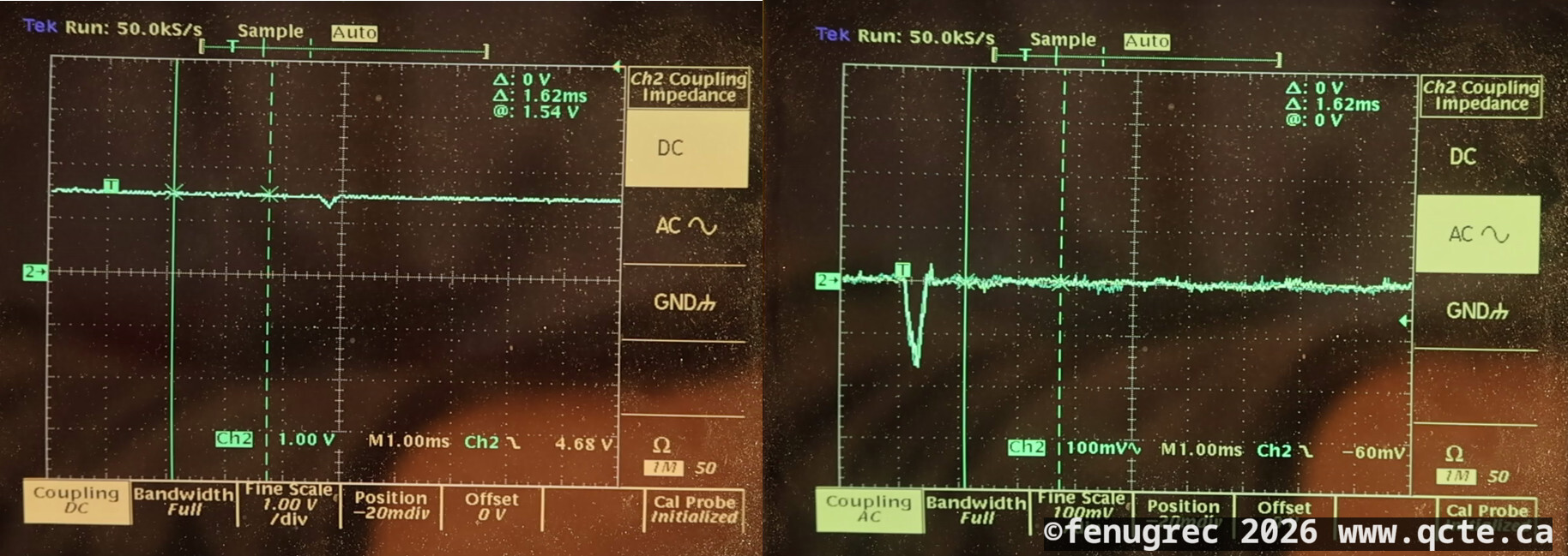
There are luckily obvious testpoints for the main supply rails, +5, +3v3, +2v5, +1v5, +1v2. They were all very clean and within spec, but the 1v5 rail was showing small dips (about 150mV deep, a few 100us wide)
!RST signal#
There are two debug connectors; 14-pin J3 (unpopulated) and 26-pin J2. An educated guess for J2 would be a Coldfire BDM debug port, with the Reset signal on pin 7; behaviour certainly seems to confirm this. This same signal was also on J3 pin 14. It would make sense for J3 to be JTAG to configure the XC3S1000 FPGA and possibly other devices, but Reset on pin 14 doesn’t seem to match any common pinout.
Initial theory was that some IC, either a voltage supervisor or (hopefully not) a watchdog IC or interlock controlled by the FPGA, was unhappy and pulling !RST down. I found only one voltage monitor, U8 (most likely MAX6457), but it’s near the +24V input section and probably controls power sequencing with no relation to !RST. The only other connection I found to !RST was the output_enable pins of U2 and U3, 74LCX541 8-bit transceivers. I set this lead aside for the moment.
Fan regulator#
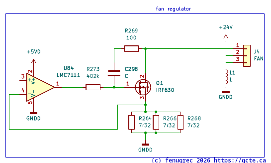
In a short dead-end after doing something that randomly allowed the unit to boot (indicated by two green LEDs on the pcb), I looked at the area around J4 fan connector, U38 LMC7111 cmos opamp. This turned out to be some kind of fan regulator, which at a glance looks like smoothed PWM input and linear drive ?
power rails again#
Decided to look at the 1.5v rail again, this time with a second probe triggering on !RST pulses. As expected, the droop on 1v5 was perfectly synchronized with !RST:
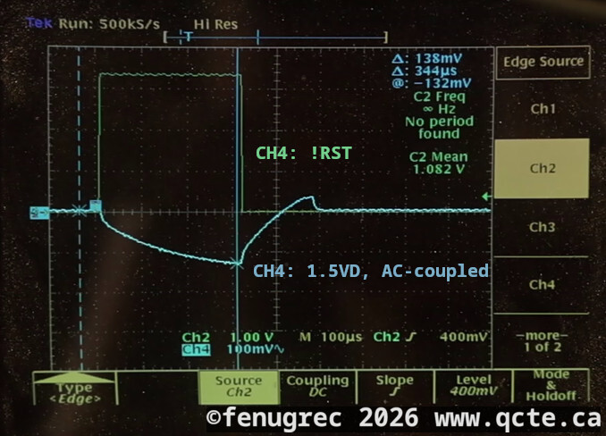
This was highly unsatisfactory, and could indicate either:
- faulty diode CR2 or supplies feeding U12
- faulty U12 regulator (FAN1582 LDO)
- excessive current draw on 1v5
- maybe bad filter caps ? I don’t see how that would cause this but easy to check.
Circuit producing the 1.5v rail (missing details):
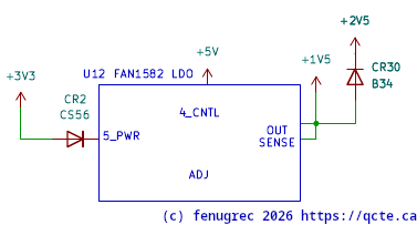
CR2 and the upstream supplies (3v3, 5v) were quickly exonerated. Filter caps tested good in-circuit, didn’t feel it necessary to remove them.
Next I connected an external 10R resistor between 1v5 and ground, to simulate adding 150mA of load. This shouldn’t be excessive for the 5A-rated FAN1582, but somehow greatly affected the droop on 1v5 (note the steeper ramp, shorter nRST pulse and longer recovery)
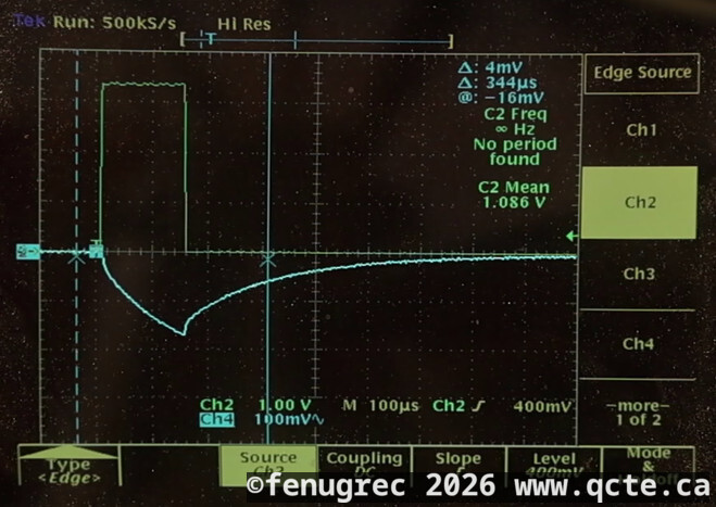
Then I used my own (now good !) 2602 SMU to inject, via a 2R resistor, some current into the 1v5 rail. In effect having my SMU “help” the regulator in parallel. At 70mA, it was enough to make the CPU survive the initial droop, and the regulator recovered enough to allow the CPU to boot !
FAN1582#
The FAN1582 and equivalent parts (EZ1582, SPX1582) are all long discontinued. In 2026 there is still some hope of finding some new SPX1582 but no regular distributor was showing stock.
These regulators are part of a family (1580, 1581, 1582, 1583) of LDOs that aparently only differ in max output current. The 1580 (rated 7A) has more cross-compatible parts like LT1580 which is in fact still available.
Finding modern drop-in replacements is not easy: the 158x are adjustable, remote sensing, and have an uncommon pinout. None of the following would work:
	*29302, 29502, 59300, 5730x...
	lp3966
	*12042
	nc*5662
	tps786
	tps7a45
	lp38513, lp3875
	ucc383
	ncp630
    and many more...
By some uncommon luck, I had, in my very own stash, some old EZ1580 stolen from… somewhere. For a test I mounted it on a thin PCB to act as a heatsink:
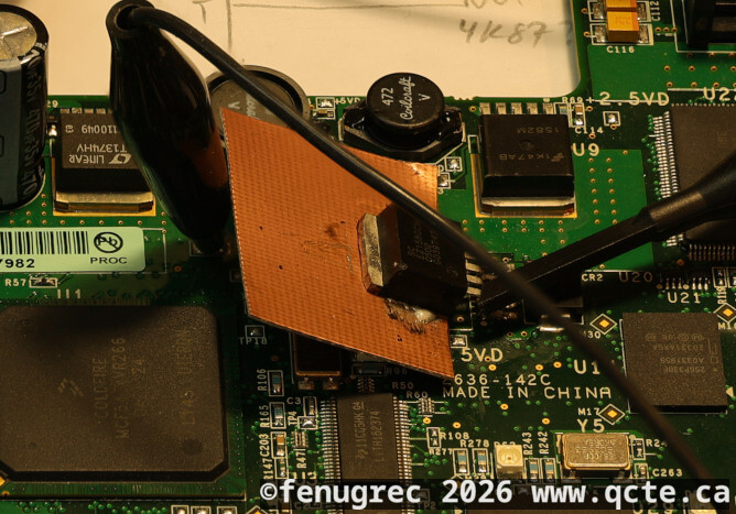
The 1.5v rail was now clean and the SMU booted normally with no external help ! I was also able to run my Performance Verification scripts on both channels with no errors.
oops#
While moving a ground clip near the 24V input, I shorted something and killed the board-mounted fuse F1. Not sure of the rating, the marking ‘4’ is not very indicative. There are no standards for SMT fuse marking; some more common schemes but none where ‘4’ makes any sense. 4A is not reasonable for this type of board; 400mA not impossible but I measured about 380mA in normal operation so that would be cutting it very close. Anyway 400mA is not a standard value; a custom ordered fuse would make little sense in this sort of design…
I will measure power again with LAN operating (and maybe a USB device plugged in); I expect an operating current closer to 450-500mA. I will probably install a 750m or 1A fuse.
Insides#
- Same PSU.
- Nearly identical DCDC board
- CPU board has more stuff, bigger CPU, LAN controller, etc but the family resemblance is there
- Channel amps: Very similar, some interesting differences. No more TO-92 bodge !!
misc test points#
*** mainpcb
+24VDC
GND
+5VD
+3.3VD
+2.5VD
+1.2VD
+1.5VD
TP5 related to !RST ? has RC decay on falling edge
TP7 same as TP5 ? didn't check continuity

J2.14 : !RST