Tektronix TDS 600/700A series oscilloscopes #
Any information present here is based on work on my own TDS 744A scope. Most of it will apply equally to other 600A/700A series models, but later -B,-C,-D suffix machines may be quite different in some regards.
Internal Debug connector #
This connector gives access to debugging output during boot, and an interactive vxWorks shell during runtime. Much information about this was scattered on the old Tek forums. Thankfully Internet Archive saves the day again. Don’t forget to donate…
- https://web.archive.org/web/20221224123349/https://forum.tek.com/viewtopic.php?t=138100
- https://web.archive.org/web/20221224172145/https://forum.tek.com/viewtopic.php?f=568&t=138489&p=280292
- https://web.archive.org/web/20221223140408/https://forum.tek.com/viewtopic.php?f=568&t=137307
Tek however decided to axe the old forums in favour of a shiny new abomination sometime in 2022. Most of this section is from forum posts there (I don’t remember the original authors), and screenshots from service manuals.
The cardedge connector needs an external board with a MC68681 DUART, which may be hard to obtain now unless
- re-using the Opt.13 rs232/parallel card (easiest, described below)
- (untested): HDL implementation, https://github.com/silverchris/MC68681_Verilog
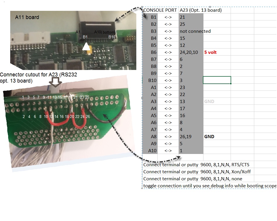
Opt.13 wiring #
(“B” is the row on top of PCB)
Console port - Option 13 Board - (Signal Name)
A10 - 1 - (D24)
B10 - 3 - (D25)
A9 - 5 - (D26)
B9 - 7 - (D27)
B8 - 2 - (D28)
A7 - 4 - (D29)
B7 - 6 - (D30)
A6 - 8 - (D31)

B1 - 21 - (A1)
A1 - 23 - (A2)
B2 - 25 - (A3)
A2 - 22 - (A4)
+5V (B6) - 24 - (A5)
GND (A3/A8) - 26 - (A6)

B5 - 12 - (INT#)
B4 - 15 - (IOCS#)
A5 - 16 - (SYSRESET#)
A4 - 17 - (RNW)

A3, A8 - 9, 13, 19 - (GND)
B6 - 10, 20 - (+5V)

B3 - not connected

not connected - 11 - (DS#)
not connected - 14 - (DSACK0#)
not connected - 18 - (AS#)
Notes:
- As displayed in the “TDS520B Mod CM” service manual, On the console port “B” is the top side of the processor board.
- Signals A5 (Pin 24) and A6 (Pin 26) need to be set to +5V and Gnd to make sure the serial port of the option 13 board is selected. [ EDIT - careful, this refers to signals A5 and A6 respectively, not ‘connector positions A5 and A6’ ]
- The 3 ground pins (9, 13, 19) should be connected on the option 13 board, so normally you only need to connect one of these to the console port connector.
- The 2 +5V pins (10, 20) should be connected on the option 13 board, so normally you only need to connect one of these to the console port connector.
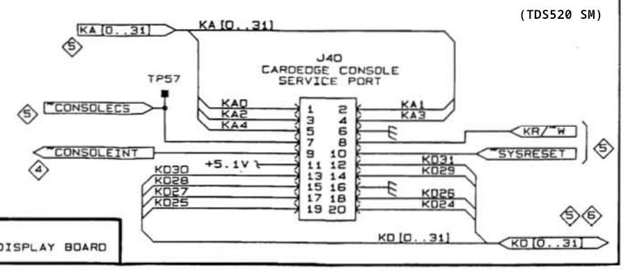
Schematic screenshots #
I believe TDS520, 544, 644 etc all have compatible J40 pinouts.

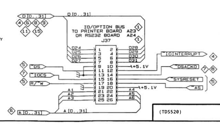
TDS520 Opt.13 connector
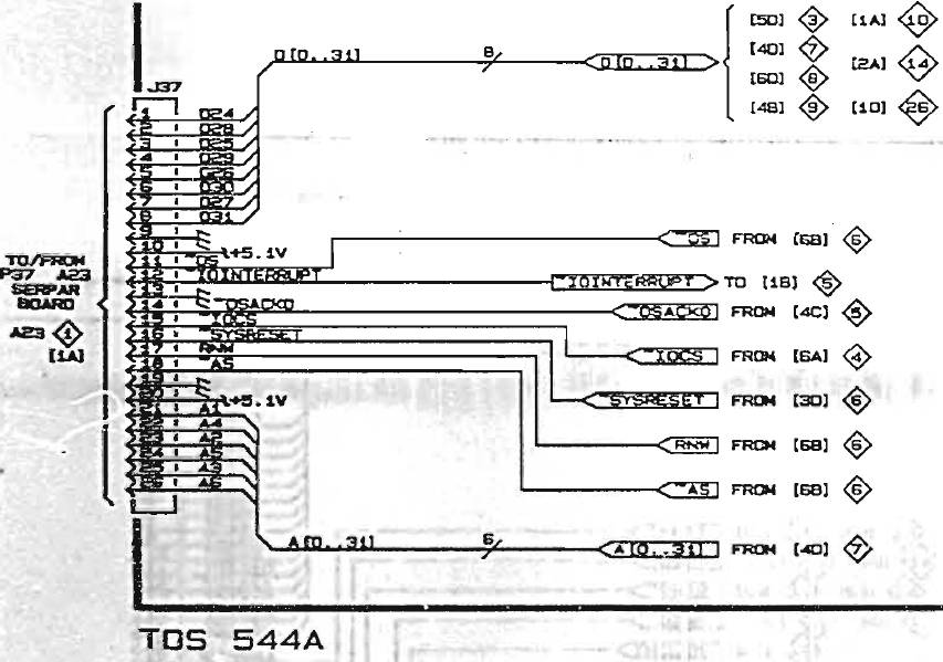
TDS544 Opt.13 connector
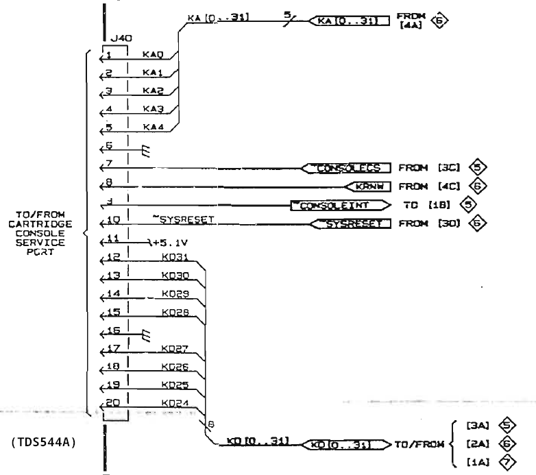
TDS520 J40 console port
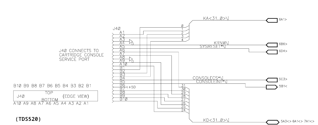
TDS520 J40 console port, original schem numbering
TDS544 J40 console port