The Fluke 2640A and 2645A NetDAQ combine a DMM and built-in 20-channel scanner. By contrast with the earlier 2620/2625 models, these are mainly controlled via TCP/IP instead of RS232. While there is an RS232 connector on the rear panel, this only gives access to a limited SCPI-like command set, mostly for calibration.
Links #
- https://github.com/Doridian/NetDAQ/ - python interface
- https://github.com/fenugrec/netdaq_utils - reverse-engineering stuff
Ethernet TCP/IP interface #
Fluke elected not to expose an SCPI command set on the ethernet interface, instead going for an undocumented (of course) binary protocol. Luckily someone already did most of the work documenting the commands and implementing a python interface. The official alternatives are:
- FlukeDAQ v3.02 available here, runs nicely in a winXP VM. And I heard rumors (cough) that patching the opcodes at 0x20e50 and 0x274DD would get rid of the 60 minute time limit…
- FlukeDAQ v6.0.4, still available here, has a more ‘generous’ 40-hour time limit. Can also run in a VM
Undocumented ports #
The firmware has evidence of opening two additional ports, at ’normal_port + 1’ and +2. Nmap confirms the +2 port (ignore the ‘SERVICE’ column; 4369 is the normal_port)
$ nmap -PS -p4300-5000 192.168.3.40
Starting Nmap 7.95 ( https://nmap.org ) at 2025-03-18 14:47 EDT
Nmap scan report for 192.168.3.40
Host is up (0.018s latency).
Not shown: 699 closed tcp ports (conn-refused)
PORT     STATE SERVICE
4369/tcp open  epmd
4371/tcp open  l2c-control
Shame. Expected 4370 to be open as well; possibly exposing commands 0x1F4, 1F5.
Port 4371 : Cmd 0xcb should return 0x7d4 bytes of some unknown crap. Untested
Interesting that 0x1f4 = 500; 0xC8 = 200
RS232 commands #
Many of these are documented in the service manual. Command names : upper/lowercase doesn’t matter. I may not update this list very frequently; planning on a better (versioned) list in my netdaq git repo
Command list #
******************************************
commands sorted by 'levels' (meaning unclear).

Level 5:
	- autarch
	- *idn?
	- *opc?
	- *lcv?
	- *rst
	- cal_const?

level 4:
	- cal
	- cal_ref
	- cal_ref?
	- cal_step?
	- cal?
	- cal_clr

level 2 is special. Only works if prefixed with `autarch;` on the same line ? :
	- memory?
	- cal_const_commit
	- cal_const
	- baud
	- boot
	- reboot
	- button?
	- eaddr
	- eaddr?
	- eem_clr
	- est?
	- c
	- c?
	- dump_ec?
	- mem_show?
	- port
	- net_params
	- net_params?
	- fdvp_state
	- fdvp_state?

level 1:
	- *tst?
	- func
	- func?
	- meas?
	- selftest?
Regular command descriptions #
**** cal_const? <n>
reply: +1.00069E+0

get a 32-bit float cal constant, where <n> is an even number from 0 to 60.


**** FUNC? 1
reply: VDC,AUTO

arg must be 1; only queries mode for channel 1.

**** FUNC 1,VAC,AUTO
**** func 1,ohms,auto,4

sets function mode of chan1 only

******************************************
'autarch' mode commands
these commands must have 'autarch' on the same line; it sets a special mode, temporarily


**** autarch;reboot
reboots

**** autarch;boot
reboots into 'boot monitor' / bootloader mode

**** autarch;button?
reply: <numeric ID of last button pressed?>


**** AUTARCH;net_params?
reply: 1,GEN,4369,192.168.3.40

probably <BCN>,<ISO|GEN>,<port>,<ip>

**** autarch;dump_ec?
dv->status = 0x4000, dv->intenable  = 0x8080, dv->mode = 0x241, dv->config = 0x5E28, dv->txstart = 0x106, dv->DMA = 0x8080, dv->tranceiver = 0x40

**** autarch;memory?
12764

not sure what this value represents

**** autarch;eaddr?
00:80:40:00:13:b0

get MAC address

**** autarch;mem_show?
output is on A1 internal debug port !! (38400bps 8n1)
**********************
FREE LIST:
  num     addr      size
  --- ---------- ----------
    1    0x7d8f8       9984
    2    0x28258        288
    3    0x16bf8      12772


SUMMARY:
 status   bytes    blocks   avg block  max block
 ------ --------- -------- ---------- ----------
current
   free     23044        3       7681     12772
  alloc    408044      116       3517        -
cumulative
  alloc    410060      123       3333        -
**********************
Boot monitor commands #
After entering bootmonitor with autarch;boot, the interface will respond to these commands :
Boot monitor commands:
	B	Attempt to reboot
	C	Compressed binary S-record
	L	Launch Application
	R	Copy RAM to Flash
	S	S hex record (S2 or S3)
	T	Test Code image
	V	Print software versions
	?	Print this
0>
Software versions:
Boot monitor: BM02.08
Boot lomem table: 2
PGA version: LM02.03
07/14/95 11:20:32 EllaBoot_02_08

Ella Felix: MM02.00
Ella lomem table: 2
PGA version: LM02.03
08/03/95 16:57:04 Ella_02_00
0>
Internal debug ports #
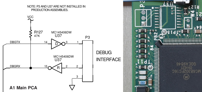
The A1 card has an unpopulated connector P3 (38400bps, 8n1) which I believe configured as vxworks stdout and stderr; some commands produce output there. I don’t know if it responds to any commands sent to it, however.
The A3 card has P1, 19200bps 8n1, rs232 levels. To activate this, unit must be reset with a jumper on A3.W5.
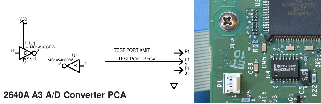
Adapter cable pinout for A3.P1 to DB9-male plug:
- P1.1 DB9M.3
- P1.2 DB9M.2
- P1.3 DB9M.5 (gnd)
A3 boot monitor commands #
Very similar to A1 bootmonitor:
Boot monitor commands:
	B	Attempt to reboot
	S	S hex record (S2 or S3)
	T	Test Code image
	L	Launch Application
	V	Print software versions
	R	Copy RAM to Flash
	?	Print this
0> V
Boot monitor: BA00.09
Boot lomem table: 2
04/27/94  9:53:03 OscarBoot_00_09

Oscar PFE Rev D: PA01.00
Oscar lomem table: 2
08/10/94 16:13:22 Ray_01_00
0>
A3 ‘inguard shell’ #
Reverse engineering the firmware indicated there is traces of an interactive shell, but I was unable to activate it. It would provide :
******************************
Inguard shell commands
******************************
"PEEKW M   -- read word"
"PEEKB M   -- read byte"
"DUMP  M N -- dump N bytes starting at M"
"POKEW M X -- write word"
"POKEB M X -- write byte"
"SET M B   -- set bit B at location M"
"CLR M B   -- clear bit B at location M"
"TST M B   -- read bit B at location M"
"WS R X    -- write Stallion register R with X"
"SETUP F   -- set function relays and stallion for func
"CHAN C F  -- same as SETUP F, but also select channel C"
"CHANDEF   -- print out current channel definitions"
"CONFIG    -- print out current global configuration"
"V         -- print out version information"
"REBOOT    -- hard reset"
"?         -- print this message"
Firmware #
I didn’t want to desolder the flash ICs, so I opted for a ‘passive’ dump approach, presented in this YT video. The downside is that since I’m only ‘spying’ on the address + data lines, I rely on whatever ROM checksum functionality the firmware has, that reads all locations sequentially. The same approach was used on both the A1 mainboard and A3 Analog boards.
- A1 firmware (BM02.08, MM02.00), 0x00000 - 0x5 BACB, with blank Cal block
- A3 firmware (BA00.09, PA01.00), 0x00000 - 0x1 072C, with blank ‘parameter’ blocks
2640A vs 2645A #
As far as I can tell, the A1 firmware would be identical in both variants, but I’m fairly certain the A3 (ADC board) is different. I only have a 2640 here.
Dump process #
This proved to be a bit complicated, because the ROM image is divided into
- boot image and its own (fragmented) checksum loop
- ‘parameter block’, holding the cal constants, that is AFAIK not checksummed
- main image, with the sanest checksum loop so far (the A3 firmware is structured the same, but without a parameter block)
Reverse engineering #
I made some tools to assist RE work. I may post my ghidra project files eventually in that same repo. This work resulted in the discovery of some hidden RS232 commands, some (apparently inactive) debug consoles, and undocumented TCP/IP ports.