The Agilent ESA E440x series (E4401B, E4411B, E4402B, E4403B, E4404B, E4405B, E4407B, E4408B) spectrum analyzers are all very similar and share a number of parts. Of these, the 1.5GHz units (E4401 / E4411) will not be further discussed here since they use an entirely different RF deck assembly.
All the others use the same RF deck part # E4403-60087, which has well known problems in the divider chain of the PLL. Agilent has changed the design a few times, but for some reason their custom divider MMIC always proves to be the weak link.
PLL divider #
Symptoms of failed divider IC #
This is fairly well documented. ‘LO unlock’ error is the main clue. Of course, none of these observation are a guarantee that the divider IC is the culprit; there is a complex signal chain and any of its components could cause similar symptoms.
- Two red LEDs (labeled
LO TOO HIGH/LOW) may be blinking alternately, or one of them may be solidly on, indicating the PLL loop is saturated or hitting both limits. - Probing around the divider is challenging : YIG signal comes in at ~ 3-8 GHz, first prescaler stages bring this to ~ 1-2 GHz, still difficult to measure without… another spectrum analyzer.
- It should be possible however to look at the Phase detector signals (less than 10MHz by then) with a scope; there are convenient testpoints labeled
REFERENCEandFLO/N.
Early (?) model #
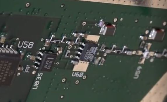
(let me know if you have a better photo and/or schematics of this variant, the above photos are not mine). This is the better-known version, using a fixed divide-by-4 MMIC (U60, 1GC1-4207, SOIC-8) and is very well covered on youtube. The HMC365S8 is a drop-in replacement and easy to install.
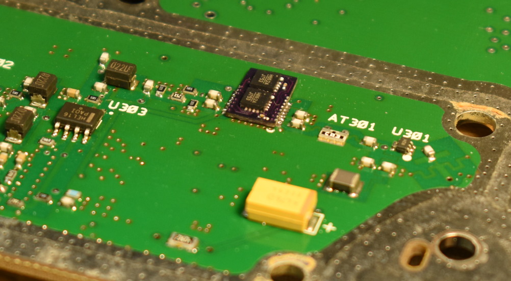
Late (?) model #
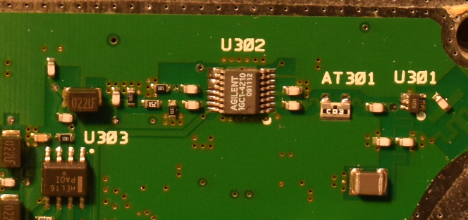
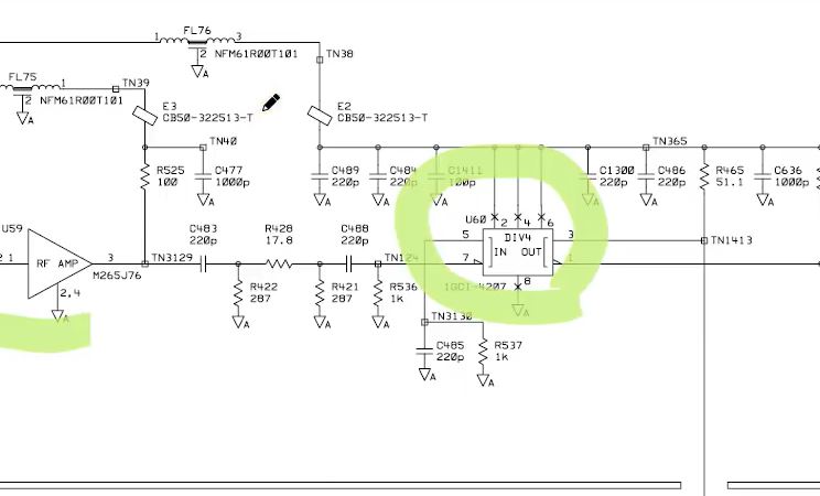
This one is more challenging. There is no off-the-shelf replacement part for this multiple-ratio divider (selectable 1,2,4,8,16). I traced part of the divider section schematics:
Because A2 and A3 are tied together to +5VD, the only ratios used are :8 and :16. But this is still not possible with one single IC, and therefore an adapter PCB is required.
1GC1-4210 replacement #
While there are online sellers claiming to have this IC in stock, the source is questionable at best, and given the poor track record of even those supplied by Agilent, I feel there is no point in even trying a second-source part. Best scenario is a used pull that may fail soon, worse case is a complete dud.
Thankfully (?), the same MMIC also often fails in some Agilent ESG signal generators, and the problem has been solved and tested already, using two HMC862 dividers (1/2/4/8). These boards are sometimes available pre-built, or as an orderable PCB :
I was considering building a few and decided to have my own PCBs built by OSHpark. The design looks like this:
I used the “2oz-0.8mm” option for its thinner PCB material; 2oz copper was not really necessary. I recommend panelizing a few copies of this manually, to ensure a clean routing pass on the sides with the castellations. Otherwise OSHpark may put mousebites there, requiring some extra sanding to get the shape right.
Note that this design pushes the limits of OSHpark specs, and they may refuse (or fail) to manufacture it. KiCad design files available here. I didn’t “share” the design on OSHpark for the reasons above.
RF Assembly versions #
I think it should be possible to correlate the ass’y revision to the type of divider IC used. This would be convenient since taking apart the RF deck is quite a task. The revision number can be obtained via the software by looking in the System (2) -> Show Hdwrd page, at the line “50ohm 3GHz input”.
I would be interested in more datapoints, please contact me if you have further info.
- ?, uses 1GC1-4207 followed by MC12095
- E440360107, serial 231005xxxxx, rev 05 A, hw ID 82 : uses 1GC1-4210
- E440360107, serial 231048xxxxx, rev 05 A, hw ID 82 : uses 1GC1-4210