This is a fairly recent multi-channel USB audio interface. I think there’s a distinction between the “Presonus 1824c” and “Presonus Studio 1824c” ? Not sure. The PCB (and internal software naming) calls this generation “nemesis”; the 1824 (without ‘c’ sufix) would be “dante”.
Repair #
Chapter 1 : caps #
Of course a YT repair video; also includes a deep dive into measuring Equivalent Input Noise (EIN) to validate specifications.
Again, consumer electronics plagued by toilet-grade capacitors. This time, luckily no corrosion damage (that seems to be confined to caps from the ’90s).
The culprits :
- first bulk cap (C4) after a PMOS switch, with visibly domed top
- a few others with in-circuit measured capacitance & ESR clearly off
- a few that are paralleled on the
switched_12Vrail, and had to be removed to be measured properly

At this point, it almost worked but was flaky still ; probing the +5, +3.3 and +1 rails I could see it was trying to power-on and failing repeatedly (ramp-up followed by a collapse, repeated on all rails). Unfortunately, forgot to get scope screenshots. It appears the +3.3 and +1 regulators are fed from the +5 rail (but why ?), and the +5 rail had a marginal capacitor that I had initially overlooked. After replacing a few more, power-on became solid.
List of questionable (and replaced) capacitors #
| desig. | val (uF) | V | dia | H | pitch | orig type | where |
|---|---|---|---|---|---|---|---|
| c19 | 100 | 25 | 6.3 | 11 | 2.5 | jamic | |
| c21 | 100 | 25 | 6.3 | 11 | 2.5 | jamic | 5v |
| c22 | 100 | 25 | 6.3 | 11 | 2.5 | jamic | filt vcc_sw |
| c23 | 100 | 25 | 6.3 | 11 | 2.5 | jamic | filt vcc_sw |
| c29 | 47 | 63 | 6.3 | 11 | 2.5 | Crapxon KM | phant |
| c345 | 100 | 25 | 6.3 | 11 | 2.5 | jamic | |
| c374 | 10 | 63 | 6.3 | 11 | 2.5-5 | nichi VR | phant |
| c380 | 470 | 16 | 9 | 10 | 5 | yuscon RM(P) | |
| C4 | 1000 | 25 | 10 | 20 | 5 | teapo a3 tx | |
| c454 | 220 | 25 | 6.3 | 11 | 2.5 | Crapxon gs | 3v3 rail |
| c455 | 470 | 10 | 6.3 | 11 | 2.5 | hy LESR | |
| c90 | 100 | 25 | 6.3 | 11 | 2.5 | jamic | filt 5v U22in |
Chapter 2: clocks #
Also a YT video for this part.
I thought I was done after the first round of capacitor replacements. I soon realized the interface would not work at sample rates 176.4k and 192kHz : the display would show maxed-out bargraphs on every channel, and produce only noise (if anything; I found it was also somewhat flaky and unresponsive in this state). I initially, and wrongly, suspected the linux driver and some recent commits. One side-effect of one tangent I took during that investigation: I made a wireshark dissector for some of the proprietary vendor requests dealing with internal mixer. Not really relevant or useful in this case; sample rate is managed using class-compliant USB-audio mechanisms.
I’m not the first to see this issue as shown in this unresolved thread.
I also went 12 rounds with presonus ’tech support’ (fairly sure I was talking to some garbage AI agent…), and after jumping through the standard hoops, was informed they
- don’t provide schematics or service manuals (industry standard…)
- don’t provide parts anyway ! (?? focusrite are perfectly happy to do so…)
Very nice. What a waste of time. Allow me to summarize the troubleshooting steps :
- revert to factory default firmware
- re-upgrade to latest (probably v3.11) with UC software.
- suspect the hardware. Claim warranty if possible.
ALSA plugins #
First, my testing method was flawed : arecord -r 96000 -D 'sysdefault:CARD=S1824c' .... doesn’t necessarily configure the hardware for 96khz, because of the ‘sysdefault’ plugin. How alsa plugins such as ‘sysdefault’, ‘hwplug’, and ‘hw’ behave vs requested samplerates is a bit obscure.
It’s helpful to add -vv --dump-hw-params --disable-resample args to arecord for more information. I was also running wireshark to examine how it was changing rates.
Windows 10 ? #
I finally revived a native win10 machine to test the official software + drivers, and confirmed that the problem occured there, and thus was not a linux issue.
USB-audio is not simple #
Looking at USB-audio descriptors in wireshark was enlightening, but also daunting. The main takeaways for the 1810/1824 interfaces :
- ‘interface’ 1 is for playback, interface 2 for capture
- those interfaces have 4 possible ‘alternate settings’ :
- alt 0 = off, no audio data
- alt 1 : 18ch, up to 48kHz
- alt 2 : 14ch, up to 96kHz (we lose 4 of the 8 ADAT chans)
- alt 3 : 8ch, 176.4/192kHz (no ADAT, and no SPDIF)
In addition, changing sampling rates involve some CX_CLOCK_SELECTOR_CONTROL and CS_SAM_FREQ_CONTROL requests.
Internal clocks #
Opening up the interface again, I probed around, initially hoping/suspecting some more dubious caps i.e. around the ADC / DAC sections, or the cpu core. This was fruitless; I then located important clock signals and found the following:
The master clock MCLK originates around the clock-gen area, is routed to ADC and DAC, and is very clean at both ends. T215 is near under the main CPU; at the other end it was necessary to probe the DAC pin directly:
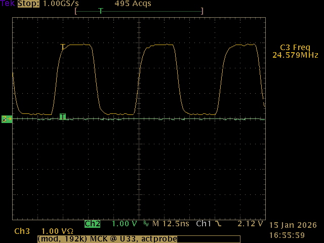
Very clean, no problems there. BICK/DCLK however is another story; compare when sample rate is set to 48k vs 192k:
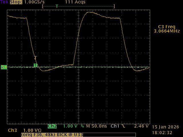
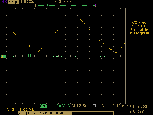
Notice different 4x difference in time scale; what simply looks like a slow rise time at first glance, becomes almost a triangle wave! Also, looking more closely, why does the 3Mhz signal dip so far below ground, and has a huge overshoot over 3.3V ?
BICK filter #
Some (lengthy) probing finally led to this section on the PCB:
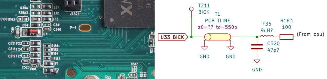
The “PBC TLINE” is a rough equivalent of the ~120mm stripline/waveguide that leads to the ADC + DAC chips. I can only guess at its parameters, and estimate an impedance of 70-110 ohms. I’m not sure why they have C520=47pF (measured 52pF in-circuit, not sure how much of that is due to the transmission line).
Component F36 is interesting. It looks and tastes like a ferrite bead, but it seems to have a fair amount of inductance at low freqs, around 5-10uH !? With F36 removed, the signal from the CPU is as expected, a very square, fast-edge square wave. Clearly this filter network is mangling the clock signal; I can’t possibly imagine why this would be done on purpose, so maybe an odd failure mode of the ferrite bead ?? I’d be curious to look at this same clock signal on ‘good’ units.
I tried to characterize F36 on my hp4195 but have low confidence in my test setup and results:
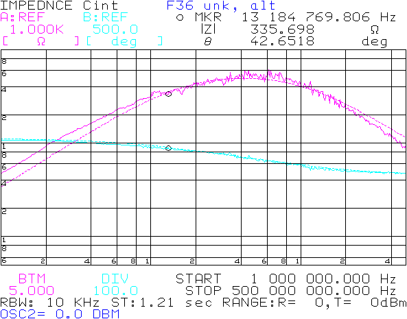
The dotted line trace is an estimated equivalent parallel circuit of 5.4uH // 2.7pF // 492R. As shown, near the BICK frequency 12-13MHz, it has a quite high lossy impedance of 335R@45deg.
Transmission line #
I modeled the ‘filter’ and tranmission as best I could, and surprisingly was able to obtain a very similar characteristic, both for 48k (BICK=3MHz) and 192khz (12MHz):
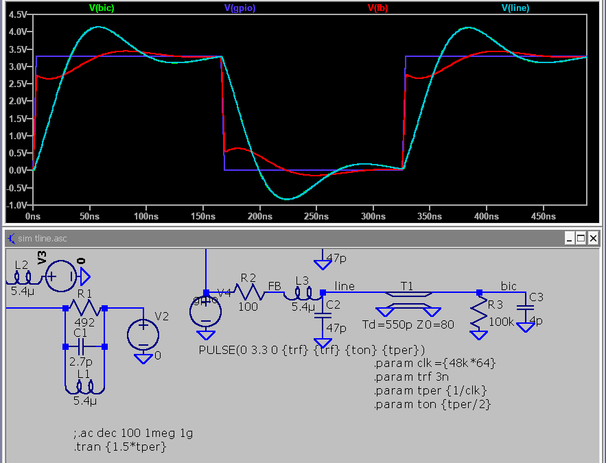
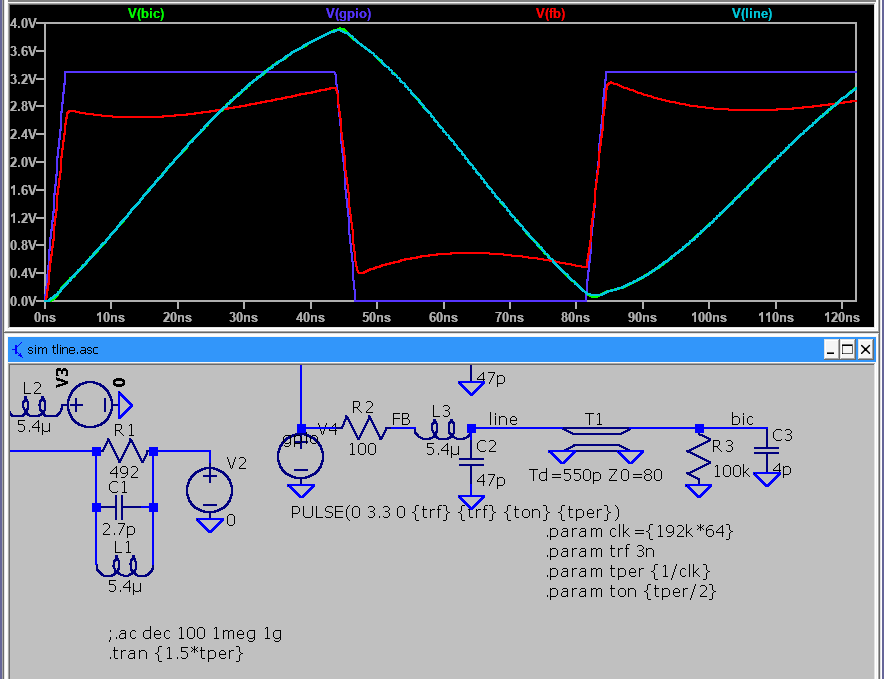
Not an exact match of course, but the general aspect is very much the same. I’ll just drop some smart words with a bit of hand-waving: something to do with an open-end transmission line, reflections, mismatch, that sort of thing.
F36 replacement #
Hard to guess the designer’s intent here. R183 + C520 is a substantial RC filter (~ 34Mhz corner), did they want to slow down the edges that much ? If so, why not do the same on MCLK too ? Is it just a way to slightly delay BICK ? Anyway, I decided to install a less agressive ferrite bead I had on hand (CB1608-600 : 60ohm @ 100MHz; about 15ohm inductive at 13Mhz i.e. 200nH). Here’s BICK at T211 after this mod :
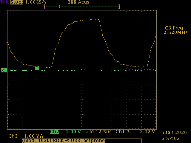
Eh, not great, I can still sortof imagine some reflections in there; the slow edges is simply the effect of the original R+C filter.
The import part : it now works !!
Testpoints #
These are under the PCB.
- T3 !phant_en ?
- T7 5v (C21?)
- T11 +1v (0.94v)
- T17 +15v
- T18 -15v
- T27 phant +48V if !phant_en
- T29 3.3v (C454)
- T211 BIC/DCLK (64*f_spl)
- T213 f_spl
- T215 MCLK either 22.579 or 24.571Mhz, the former for 44/88/176.4khz rates, the latter for 48/96/192 ?
Components #
- IS25LQ016 SPI flash, 16Mbit/2MB
- TL082 : Ch1&2 (Instrument hi-z pre ?)
- HP amp : njm4556AL
- U5 MP3425 step-up for +48 phant
- U7 NCP3170A; vin=4.92V, vout=1V
- U16 NCP3170B; vin=vcc_sw, vout=5.1v
- U22 NCP3170B; vin=4.99V, vout=3.3v
- U29 MP3425 step-up for +/-15 rails
- Q3 : NT2955G, onsemi, Pmosf (input pwr switch)
- Q1x,Q2x (to92, 2 per input), 2N4403 PNP
- Q3x,Q4x (sot-23, 2 per input channel) : BC849, marking 2C
ncp3170a/b pwm controller variants: (-A = 500khz, -B=1Mhz)
display PCB:
- n79e715 nuvoton 8051 mcu
- 2x IS31FL3728 (qfn24 LED matrix driver)
Preamp noise (EIN) #
Long story short : about -129dBu(A) on each channel (with 150R dummy plug), vs specified -128dBu. Nice !
Spurs / intermodulation #
Less nice : the bargraph display is multiplexed at ~ 3.2kHz; in my unit one mux is running at 3.14kHz for the input bargraphs, the other mux at 3.21kHz for the buttons and the Main_out bargraph. Both of these, in certain situations, can bleed into the input signals ! The more LEDs are lit, the worse.
There is also some kind of modulation when a large amplitude tone is present : spurs appear on both sides of 3.2kHz, and at a strangely higher amplitude than the 3.2k fundamental:
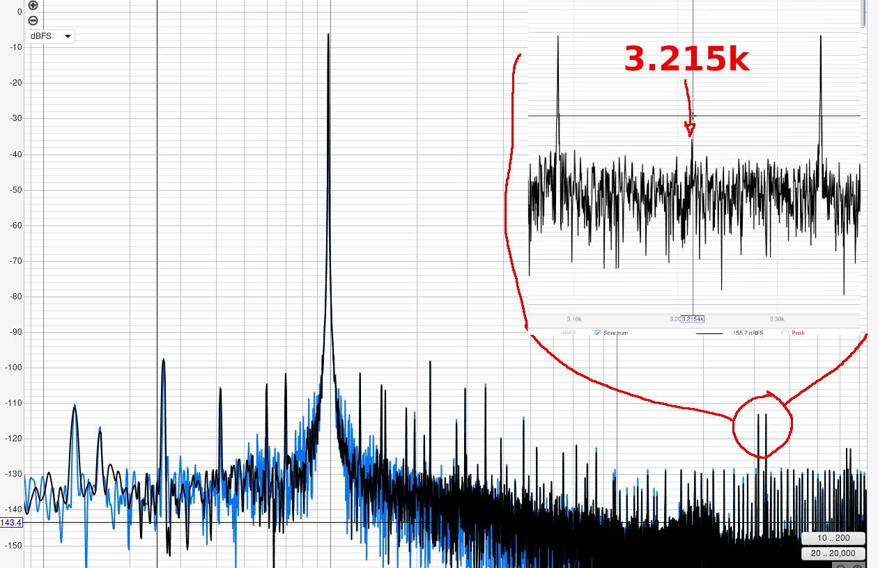
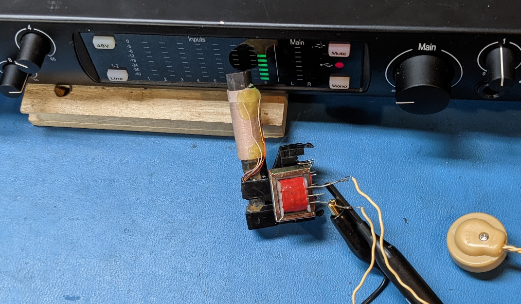
Confirming the source was fun : an AM radio ferrite stick, 12:1 audio transformer, and piezo earphone :
Unclear how exactly this is happening, and even less sure how to fix it. I’ve determined:
- some channels are more affected than others, so it’s not simply noise getting into the ADC
- the display PCB also has gain/volume pots for channels 1-4. Some traces go right accross both areas ?
- LED supply rails are separate from analog +/-15V, but GND is necessarily connected in some (unknown) way
- back of display PCB has ‘high current’ traces at the surface
Firmware #
*********** Note ! **********
At some point after the USB DFU tests, I took many wild tangents because a tool I was using, was not behaving as expected. I still think there is interesting material here; and after all the trouble I went through, and having written this concurrently, it would be a waste to erase it… TLDR: skip to the end
Initial poke #
Let’s see if I can extract firmware updates from their software “Universal Control”. Looking through the installed files, it doesn’t look like the firmwares are separate files, but rather either bundled in an .exe, or retrieved online.
First, the easy stuff :
$ strings Universal\ Control.exe | grep firmware

firmwareRevision
firmwareVersion
firmwareUpdateNeeded
.......
firmware.json
Good guess; they have firmware update code inside the .exe. What is this .json file though, is it obtained online like Tascam does for some of their things ?
A bit later, still in Universal Control.exe, I find a few bits like
                "defaultfilename": "fpclassicupgrade.syx",
                "successcode": 2007,
                "firmwareupdaterequired": false
                "devicemodel": "FaderPort 8",
                "portname": "PreSonus FP8",
                "portname.mac": "PreSonus FP8 Port 1",
                "updatedelay": 200,
                "parts":
                        {
                                "revision": "343",
                                "version": "v3.43",
                                "file": "firmware/fp8upgrade.syx"
Hmm, definitely json syntax, but I can’t find an entry for the 1824c. The above is for different hardware, reflashed over MIDI (the .syx extension, for SysEx).
Not much luck in other files. Note, the 1824c is part of the “studio” series; internally referred to as ’nemesis’, and handled by the “StudioUSB” driver.
FW versions #
So, what happens when I plug this in, with a VM running UC 3.2.1 ?

What, my unit has v3.11 and UC wants to flash the “new version” 2.51 ? Uh…. I assume it’s only checking for an exact version match; obviously not a numeric ‘greater-than’ comparison.
A bit of release note archeology reveals :
- product probably initially shipped with fw 2.50; UC 2.10 is the first to support the series
- UC 3.2.1 upgrades fw to 2.51
- some products shipped with 3.04 at some point, according to this user
- UC 3.6.3 first mention of fw 3.11
Not sure of any other intermediate or more recent fw versions.
So where is that fw blob hidden ? I’m omitting tons of false leads here, but I dug a bit deeper with binwalk, with the essential argument -a which continues parsing within .exe / .dll after their header; thus I found lots of compressed XML data. This wasn’t the revelation I hoped, but still found an interesting chunk :
	<Variant property="incompatible" .....
		<Link title="PLEASE UPDATE DEVICE FIRMWARE!" command.category="Settings" command.name="Update Firmware"
Right, so they probably expect an exact version match. This also explains why it was hard to search for UI strings - they are compressed ! The interactions are complex between Universal Control.exe and the supporting framework cclgui.dll etc.
And the disassembly in ghidra is not very revealing either - convoluted refs due to C++, classes, that kind of mess. I made zero progress on that front.
Low level SPI capture #
Before trying a fw upgrade, I wanted some kind of backup. I hooked a logic analyzer to the SPI flash IC (didn’t feel like de-soldering it), and spied on the boot sequence. With PulseView + https://github.com/mbenkmann/quadspi_sigrok/ and some scripting, I obtained a few blocks of data. It appears the XMOS cpu reads what it needs into its on-chip RAM and executes from there. The firmware is surprisingly small, about 207kB, vs the flash IC installed (2MB) !
Seems to run some code at address 0 (bootloader ?):
8D 30 00 00 F3 37 00 09 00 B7 10 ....
then a large chunk from 0x18000:
ED 15 FF 00 D0 C1 3C 22 E7 83 2B ....
And lastly, most likely a ‘config block’ at 0x10 0000:
00000000: 50 52 45 53 4f 4e 55 53 78 d1 7f be 00 00 00 01  PRESONUSx.......
00000010: 53 43 34 45 31 39 _________________ 00 00 00 00  SC4E19      ....
00000020: 00 00 00 00 00 00 00 00 00 00 00 00 00 00 00 00  ................
This last block was very nice to have as the only source of verifiable plaintext. There is no ASCII anywhere else, despite entropy being lower than expected - I fully assumed this would be encrypted, as on the Scarlett 3rd gen. Note, this particular chunk contains the serial number and is probably not contained in a fw blob but written as needed by the device.
USB DFU #
These are complicated composite USB devices, exposing USB-Audio class compliant interfaces and endpoints, MIDI endpoints, vendor-specific stuff, and in this case also one visible USB-DFU interface :
$ lsusb -v
Bus 005 Device 065: ID 194f:010d PreSonus Audio Electronics, Inc. Studio 1824c
Negotiated speed: High Speed (480Mbps)
....
 Interface Descriptor:
      bLength                 9
      bDescriptorType         4
      bInterfaceNumber        5
      bAlternateSetting       0
      bNumEndpoints           0
      bInterfaceClass       254 Application Specific Interface
      bInterfaceSubClass      1 Device Firmware Update
      bInterfaceProtocol      1
      iInterface             12
      Device Firmware Upgrade Interface Descriptor:
This is also confirmed by dfu-util -l :
Found Runtime: [194f:010d] ver=0311, devnum=47, cfg=1, intf=5, path="5-1.4", alt=0, name="PreSonus DFU", serial="SC4E19....
Surprisingly, it offers ‘Upload’ capability, i.e. reading memory ! Could we get a full fw dump this way ?
$ dfu-util -U test.bin
...
Upload  [=========================] 100%        96000 bytes
Upload done.
Received a total of 96000 bytes
96000 ? Seems rather arbitrary… The contents match the earlier SPI bus capture but clearly doesn’t contain the entire firmware. Some hardcoded limit? Missing some non-standard USB requests to dump other areas ? I never found out.
USB traffic #
It should be possible to have VirtualBox capture and log USB traffic for us, but it seems to be truncating or dropping lots of packets. This will be no good for examining a full fw reflash.
Wireshark is the obvious answer; running it inside a windows VM is possible but I was having issues with dropped packets and limited capture size ? It was a waste of time anyway : I can run wireshark on the host (linux), and capture USB traffic just fine even if VirtualBox guest VM is using the device.
To make this work, sudo modprobe usbmon was required first, then a short udev rule to set proper permissions (we don’t want to run wireshark as root):
$ cat /etc/udev/rules.d/90-wireshark-usbmon.rules

SUBSYSTEM=="usbmon", GROUP="wireshark", MODE="640"
Reflash #1 #
One advantage of having tons of flash, is to keep a ‘base’ firmware image that never gets erased, and fw upgrades are written to other pages / slots. Nice way to reduce risk of bricking during a failed reflash. Presonus website describes the recovery method:
To revert the Studio 1824c/1810c to Factory Default:

    Turn off the 1824c/1810c
    Turn it back on and just after the LEDs initialize, tap the Line button quickly 5 times.

	The Studio 1824c/1810c will then reset.
    Connecting it to Universal Control will show Firmware v2.50 for the 1824c and v2.51 for the 1810c
This seemed pretty benign; I tried it, and UC (and the USB descriptors) indeed showed the version to be now 2.50. Then I proceeded to reflash to 2.51, while logging USB traffic (earlier screenshot). I was also running x64dbg with (what I thought were) interesting breakpoints, but none of these were hit. I was hoping to locate the code handling the DFU reflash, and thence the source of the firmware blob.
It took me an embarassing while to figure out that Universal Control.exe doesn’t interact with the drivers directly, but rather does so via (AFAIK) ucnet.dll, possibly a UDP connection to localhost, and finally the background service PreSonusHardwareAccessService.exe !! This last one calls the tasty functions in PaeStudioUsbapi_x64.dll and studiousbdevice.dll
At least I should have a ‘full’ image for v2.51, that I extracted from wireshark with File->Export Packet Dissections;
the .json format makes it easier to process just the firmware data, e.g.
{
    "_index": "packets-2025-12-12",
    "_score": null,
    "_source": {
......
          "usb.data_fragment": "ed:15:ff:00:d7:9d:5b:7c:5d:23:4c:35:04:00:00:00:0c:a6:10:00:a4:00:00:00:0c:a6:10:00:40:00:00:00:00:00:00:00:00:00:00:00:00:00:00:00:43:00:00:00:c3:00:00:00:c6:00:00:00:db:30:00:00:06:f0:00:00"
        }
      }
Again, we recognize a familiar ED 15 FF … prefix from earlier. Some header or magic value ? or an xmos opcode ?
Poking PreSonusHardwareAccessService.exe #
Well, it’s a ‘windows service’, and simply running the .exe under x64dbg doesn’t work (something Access denied …) There’s the correct way to debug a win service, and there’s a few hacks, such as patching the entry point opcode and increasing a timeout to give us time to manually attach the debugger.
In this case, I change the opcode at 0x3f989, from E9 72 .... (some arbitrary opcode) to EB FE (endless loop).
Then, once x64dbg is active, restore that opcode to the original bytes, and proceed. This worked, but I found nothing to indicate that fw blobs are processed during service init. Not really surprising; probably only happens on an actual fw update.
Reflash #2 #
This time, installing UC 3.6.4 (which introduces fw v3.11), running wireshark, AND x64dbg attached to PreSonusHardwareAccessService.exe
And the success was complete, I hit the breakpoint to TUSBAUDIO_LoadFirmwareImageFromBuffer, which does exactly what it says; first argument is the buffer, and to my great surprise… it’s right inside studiousbdevice.dll . What the heck.
Earlier I had been searching inside files with ripgrep, which has a --binary flag that supposedly makes it usable for binary data, on binary files. I was wrong (it has to do with unicode multibyte encodings etc…). Now, knowing where to look, and looking for the ED 15 FF 00 header/prefix, I immediately found the firwmare blobs in that dll.
I hesitate to call this a tremendous waste of time, but… it could have been over much, much quicker.
FW blob hiding place #
Good grief. Hidden in plain sight. Here it is in studiousbdevice.dll :
                             fwblob_s1824c                                  XREF[3]:        FUN_180021cb0:180021e12(*),
                                                                                           FUN_180021cb0:180021e19(*),
                                                                                           1800b4f60(*)
      1800b4f70 ed               ??            EDh
      1800b4f71 15               ??            15h
      1800b4f72 ff               ??            FFh
      1800b4f73 00               ??            00h
      1800b4f74 d7               ??            D7h
And here is bits of code that associate that blob with some metadata, the string “Studio 1824c”, and a GUID:
void FUN_180021cb0(void) {
    ......
    strncpy(pcVar6,"Studio 1824c",0xc);
    ...
    strncpy(pcVar6,"{395FCE61-8658-0843-BB99-447D2E2D2CC6}",0x26);
    ...
    puVar2[1] = &fwblob_s1824c;
    ....
I found corresponding functions for all other supported devices, each with their blob.
It would be nice to have an automated extraction tool, but the .dll doesn’t really have metadata or symbols pointing to the blobs, and it would probably need scripting with a disassembler i.e. ghidra.